Mirror contacts – Function and limitations
Mirror contacts are one option for ensuring safety in electrical engineering systems that use electromechanical switchgear. This report indicates how mirror contacts function and what their limitations are. Safety is further increased with solutions that are compliant with railway sector standards.
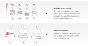
The “mirror contact” term is a relatively new term – its first use in standards only occurred in 2005. Prior to this the terms “positively driven safety contact and/or mirror contact” were used. However, this term was not specified in the standard for low voltage switching devices, rather it came about through everyday language use on the basis of the positively driven contacts according to EN 60947-5-1 for auxiliary switches or auxiliary contactors. The standard states: “If a switchgear device comprises m normally closed contacts (NCC) and n normally open contacts (NOC), NCCs and NOCs must never be simultaneously closed.” However, the definition of mirror contacts can be retrieved from the standard for contactors and motor starters (EN 60947-4-1). By definition a mirror contact is an auxiliary NCC, which can never be closed at the same time as the NOC main contact. It effectively acts as the mirror image of the state of the main NOC. To ensure the property, if sticking occurs, such as a slight fusing together of a main contact, the mirror contact must not close. It must remain open by at least 0.5 mm
Contact system with a fused together main contact

Essentially, a contactor comprises a coil with an armature, the main contact(s) and optional auxiliary contacts, that can be implemented as mirror contacts. If current flows through the coil, the armature is pulled in and the main contacts connected to it are closed. If the auxiliary switches are mechanically connected to the main contacts, then they replicate the status of the main contacts quite accurately. If the auxiliary switch is implemented as an NCC and designed according to the requirements of EN60947-4-1, the contacts are configured as mirror contacts. Direct actuation via the armature is also possible. With this principle, in general, for example, a plunger is fixed to the armature that actuates the auxiliary switch. However, with this type of actuation, incorrect feedback responses of the auxiliary contact can occur. Especially in the case of a fusing together of the contacts, incorrect notifications are effectively pre-programmed as a result of the design. The reason for this is that the armature is moved, together with the actuator, towards the initial position, although the main contacts are in an undefined state. Consequently, this design type is fundamentally not to be recommended and may have fatal consequences for man and machine.
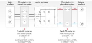
In general, the contactors used in electrical systems are actuated and monitored via programmable logic controllers (PLCs), insofar as they are not in the safety-critical parts of the system. A typical application is a test station for the inverters of electric vehicles. Normally the test piece is supplied by a switchable DC source, that is designed for voltages up to 1000 V DC and rated currents up to 1000 A. The test piece is loaded with either a permanently excited synchronous motor or an emulator. In this case contactors are to reliably disconnect the individual phases from the test piece and load. To ensure the safe disconnection of system and test piece, the mirror contacts are monitored in the feedback circuit. The main component of the feedback circuit is the safety controller, which is implemented with a safety module in smaller systems and with a safety PLC in larger ones. In this application, the safety controller monitors the integrated mirror contacts of the contactors on the primary and secondary side of the test piece. When the test is started, the test chamber is interlocked by appropriate safety technology and is only released again when the feedback circuit receives a message that all contactors have returned to their idle state.
Schematic representation of an inverter test station for the e-mobility sector

To decide whether the safety provided by a mirror contact is sufficient, the timing diagram can be considered.
As soon as the coil is supplied with current, the stroke movement of the main contact system (HK) immediately starts to actuate the mirror contact. The latter accordingly reports “HK closed” even before the end position of the main contact bridge is reached. This is necessary to ad-here to the requirements of the standard. Upon switching off, the mirror contact only enters the neutral position once the HK is fully open.
As a result of the requirements of the standards, and the mechanics of a contactor, only the open state of the main contact system can be unambiguously identified. However, the message “Main contact closed” does not guarantee that the end position has actually been reached or that in fact the main contacts are still in an intermediate position. As a result, it is possible that in both normal operation and in the event of a fault an undefined state may arise which, under certain circumstances, could lead to a dangerous situation in the form of electric arcing.
The railway industry has been aware of this problem for some time. Here too, accurate knowledge about the switch state of the contactor is very important. The defining standard EN60077 Part 2 for the railway industry resolves this problem by defining two auxiliary contact types according to the terminology of IE 600050-41. These are an auxiliary NOC a (well-closed) and an auxiliary NCC b (well-opened). These auxiliary switches signal the closing or opening of the main contact. If the contactor remains stuck half open or closed, the controller evaluates that an implausible event has occurred and can thus diagnose an error.
A typical error diagram should clarify the difference. Under unfavourable conditions, it may occur that particles of dust or dirt collect between the main contacts and prevent fault-free closing of the circuit. During closing of the main contacts, the separating distance reduces until there is a sparkover and ignition of an electric arc which is extinguished when the contacts are closed. In general, the electric arc burns off the dirt particles between the contacts, however, melting of the contact material may also occur. Dependent on the extent to which the contacts melt, they can fuse together to a greater or lesser extent. In the case of a single pole contactor with a double contact bridge or a multi-pole contactor, the drive of the main contacts may, as a result, no longer open or close correctly. As a mirror contact can only indicate the “simple” status of the main contacts and not a tilted position, there is a risk of an electric arc while the contacts are only partially open. If the current flow is not interrupted, then the electric arc continues to act, with the result that the contactor burns away.
Conclusion
Mirror contacts only reliably indicate the open state of the main contact. In the sense of EN60947-4-1, is not possible using mirror contacts to differentiate between a closed main contact and an intermediate position that arises, for example, as a result of contact fusing. Consequently this requires additional actions. By contrast, the auxiliary contact types that are widely used in the railway industry, solve the problem unambiguously. These permit a reliable evaluation of all switch states of the main contact system. If the auxiliary contacts well-open (ax) and well-closed (bx) are correctly incorporated in the feed-back circuit, a much higher safety level is achieved without great expense. The detection of the switching position with two auxiliary contacts according to railway standard EN60077 Part 2 is therefore clearly superior to designs using mirror contacts as per EN60947-4-1.
Do you have any questions?
The author Enrico Fischbach will be happy to answer your questions personally.
Simply send him your questions by e-mail.

Enrico Fischbach
Field Application Engineer at Schaltbau.


